
In my research into fitting my defi unit and gauges, I found bits and pieces of information scattered around, but nothing in one place. As such, I've put together what I hope to be a useful guide.
Defi Controller and Boost Gauge Fitting How To.
1. Wiring the Controller.
I found the best place to wire my controller was to the radio (pre harness) wires. You'll see a jumble of wires before of the connectors. I stripped back a bit of the trunking to expose more of the wires. It seems that the colours vary from some of the sources I found, so I ended up using the following diagram to source which wires to connect the controller to.
From this diagram:
![Image]()
Defi controller colour............ Radio Wiring Colour
Red......................................Battery 12V - Red/Blue (11)
Orange.................................Ignition 12V - Blue/Yellow (10)
White...................................Illumination - Green/White (4)
Black....................................Earth - Earth on back of radio
In terms of how to connect these, I found the best way was to strip the wires, splice together and solder, however you can buy snap clips which are easier, but I think there are questions over how good they are.
Once all connected, feed the controller wire down through the centre console and out near the ash tray area.
NB/ Make sure the earth is connected well. I had a small panic as my controller or radio wouldn't work. It turned out I just had a bad earth.
2. Fitting the controller.
The easiest and best place to fit the controller is on the underside of the centre console above the ashtray. It requires no panels to be taken off, and is very accessible. I used adhesive Velcro pads which allows me to adjust it to suit, and take it out if needs be (see picture)
![Image]()
3. Feeding the sensors into the engine bay.
In my case I just had boost and water temp gauges, but this can apply to whatever wires you need to feed into the engine bay. There is a grommet slightly up from the accelerator pedal (see picture 1) which leads to behind the suspension area (see picture 2). It's very fiddly to get to from the engine bay, so I removed the grommet and fed a coat hanger through the engine bay. In the engine bay I then taped the wires to the coat hanger and pulled it back through to the footwell. I then fed these wires underneath the drivers side carpet, and up to the controller unit.
picture 1
![Image]()
picture 2
![Image]()
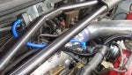
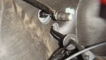
4. Connecting the boost sensor.
The following pictures show the best place I found to connect the boost pipe and mount the sensor. I used a small t, which is available from pretty much any motor shop.
![Image]()
![Image]()
5. Connecting the gauges.
I personally used an A-pillar pod (Gaz@cpp), which involved me running the cable under the driver's side carpet, and up the right hand side of the dash. There is a small panel as you open the door, which can be removed to help you feed the wire up. The A-pillar is simply removed with a gentle yank, and directly replaced with the new one. Once one gauge is connected, any others can be daisy-chained off that one.
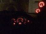
Here is the finished product.
![Image]()
If you have any questions please let me know.
Matt
Defi Controller and Boost Gauge Fitting How To.
1. Wiring the Controller.
I found the best place to wire my controller was to the radio (pre harness) wires. You'll see a jumble of wires before of the connectors. I stripped back a bit of the trunking to expose more of the wires. It seems that the colours vary from some of the sources I found, so I ended up using the following diagram to source which wires to connect the controller to.
From this diagram:

Defi controller colour............ Radio Wiring Colour
Red......................................Battery 12V - Red/Blue (11)
Orange.................................Ignition 12V - Blue/Yellow (10)
White...................................Illumination - Green/White (4)
Black....................................Earth - Earth on back of radio
In terms of how to connect these, I found the best way was to strip the wires, splice together and solder, however you can buy snap clips which are easier, but I think there are questions over how good they are.
Once all connected, feed the controller wire down through the centre console and out near the ash tray area.
NB/ Make sure the earth is connected well. I had a small panic as my controller or radio wouldn't work. It turned out I just had a bad earth.
2. Fitting the controller.
The easiest and best place to fit the controller is on the underside of the centre console above the ashtray. It requires no panels to be taken off, and is very accessible. I used adhesive Velcro pads which allows me to adjust it to suit, and take it out if needs be (see picture)

3. Feeding the sensors into the engine bay.
In my case I just had boost and water temp gauges, but this can apply to whatever wires you need to feed into the engine bay. There is a grommet slightly up from the accelerator pedal (see picture 1) which leads to behind the suspension area (see picture 2). It's very fiddly to get to from the engine bay, so I removed the grommet and fed a coat hanger through the engine bay. In the engine bay I then taped the wires to the coat hanger and pulled it back through to the footwell. I then fed these wires underneath the drivers side carpet, and up to the controller unit.
picture 1

picture 2

4. Connecting the boost sensor.
The following pictures show the best place I found to connect the boost pipe and mount the sensor. I used a small t, which is available from pretty much any motor shop.


5. Connecting the gauges.
I personally used an A-pillar pod (Gaz@cpp), which involved me running the cable under the driver's side carpet, and up the right hand side of the dash. There is a small panel as you open the door, which can be removed to help you feed the wire up. The A-pillar is simply removed with a gentle yank, and directly replaced with the new one. Once one gauge is connected, any others can be daisy-chained off that one.
Here is the finished product.

If you have any questions please let me know.
Matt
 below
below